3. Repair a loose laser unit on the Hotech ACT
I wanted to align the lower left laser as well, it's off by only a tiny bit.
When I started the collimation of this unit I saw that the laser dot moved
several centimeters on the target when I just inserted the hex key in one of
the grub screws. The red colored aluminium cylinder was loose. After a mail to
David from Hotech I received the instructions on how to fix this; unscrew the
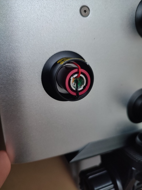
two silver set screws on the back of the laser collimator at 9 and 3 O'clock
position. This will release the front target panel and you will find the three
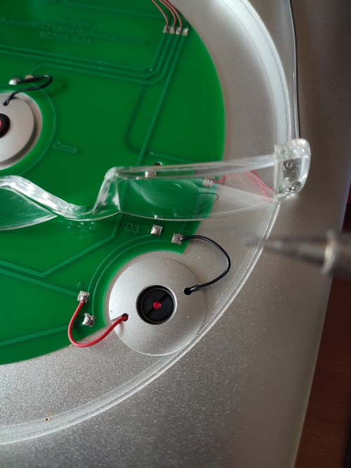
laser silver caps at 12, 8, and 4 O'clock position. The front of the laser with
the silver cap looks like this :
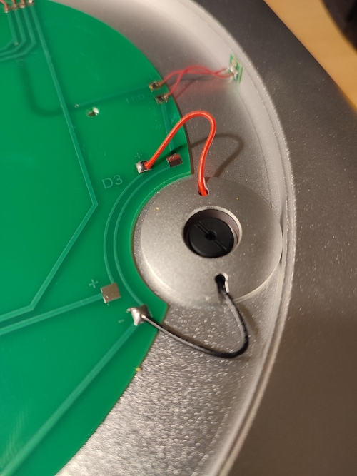
The red and black wires pass from the PCB board to the back end of the laser
unit through the holes with which the silver cap is screwed onto the black
safety cylinder at the back end of the unit.
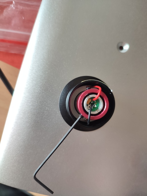
Be very careful with these wires. They break easily at the solder
points, both on the PCB side as well as on the laser unit backend side.
I think the easiest way to tighten the silver cap/black safety cylinder
combination is to hold the silver cap in place with a tool as you do not want
to adjust the place of the wiring while screwing the black safety cylinder at
the back side tight. This way you do not have to disassemble the whole unit.
This is not what I did as I wanted to see how the entire thing was held
together. Totally unnecessary of course but I'm curious and already got this
far in. So I disassembled a whole unit. First desolder the wires from the PCB,
and get them to the other side. Then use a tool to unscrew the unit.
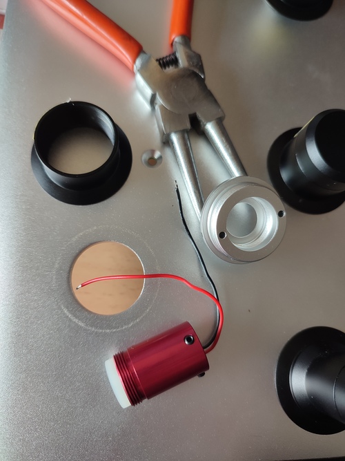
The red cylinder holds the laser units with two nylon rings at the front that
allow for some tilt adjustment at the back with the grub screws. Nice system.
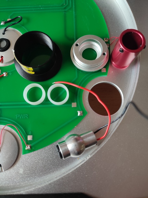
Next I put it all back together and as you can see the laser unit still works.
At this point both wires broke off at the laser unit side. But they're easy to
solder back in place if you have a soldering iron with a fine tip. After
assembly the wires were better aligned for the other solder point so I happily
made use of them. Great PCB design.
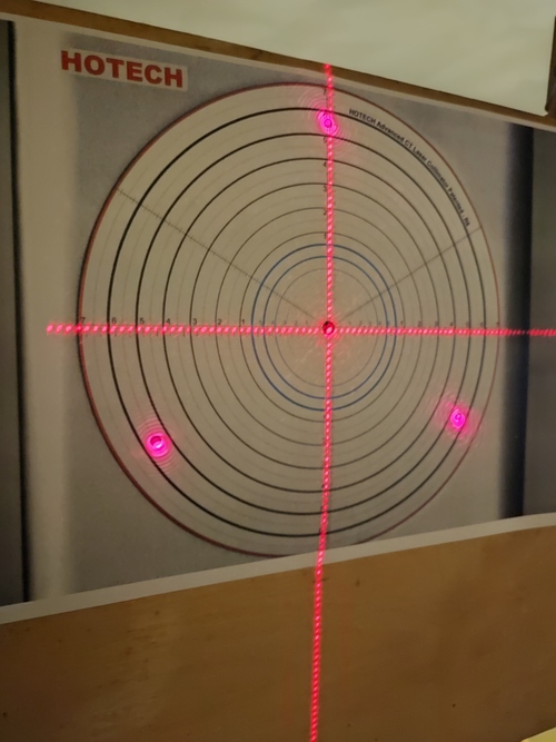
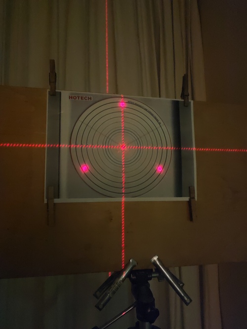
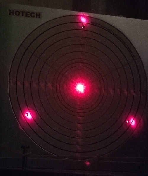
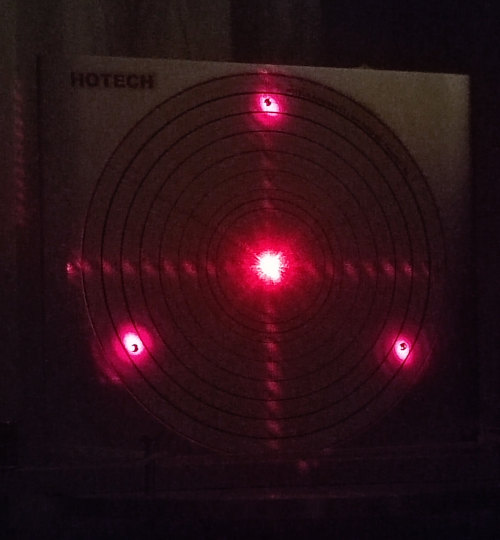
Next is using the grub screws to properly adjust the laser, from :
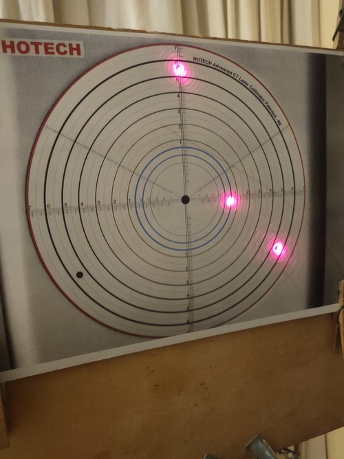
To the perfect-to-me result :
I think this is an awesome device. Thanks Hotech for making it, and making it
serviceable.
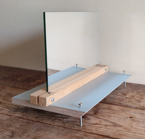
4. Further tune the Hotech ACT at 16 meters using a mirror
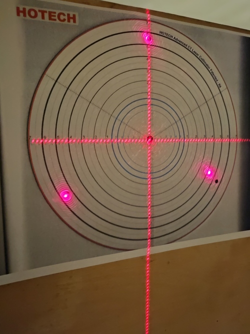
After getting quite good but still not optimal results on collimating an RC I
decided to revisit the collimation of the collimator itself. And for that I
needed more sensitivity, meaning an even greater distance to the target. The
earlier effort with a paper photocopy of the ACT at a larger distance was not
easily possible in my house, and I also did not want to again repeatedly walk
between the source and the target to see the result of a very tiny adjustment
of a grub screw. So I used a mirror that was also reflecting on the back side
(so that the beam does not pass any refracting glass) that I had still lying
around for another project and doubled the beam distance from 8.1 to 16.2
meters.
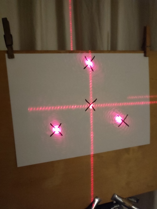
This worked really well. While the paper target at 8 meters showed all was fine
the result at 16 meters was quite different :
And the adjustments were so much easier to do, no more walking to the target to
see what the adjustment result was but instant feedback right at the source.
Why did I not think of this before ? So much easier and more sensitive.
At 16 meters distance the dotted crosshairs are becoming small diagonal lines
and the laser dots become big oval shaped blobs. I was happy with the following
result :
Last page update :
2023-08-30T21:02Z
-- Hans Lambermont